Plug And Wiring Diagram Ford Explorer 2003
Brake Controller Installation: Starting from Scratch
Before Installation You Will Need:
- Brake Controller
- 7-Way Installation Kit (#ETBC7)
- 6-Way also available
- 4-Pole Trailer Connector (if not already installed)
Information About 7-Way and 6-Way Installation Kits
The 7-way Trailer Connector Has a Total of Seven Wires:
- Four of these wires need to be connected individually, and three lead to the 4-pole adapter.
- The 4-pole adapter will plug into the vehicle's own 4-pole trailer connector, allowing for basic wiring functions without the hassle of splicing or cutting into your vehicle system.
- The three basic wiring functions are for tail lights, stop lights and turn signals.
- NOTE: This 4-pole installation is vehicle specific.
- If your vehicle does not already have its own 4-pole trailer connector, use the Wiring Fitguide to find the harness recommended for your vehicle.
The Colors of the Remaining Four Wires:
- The first wire (black) runs to the vehicle's battery to supply power to the trailer connector.
- This wire is called the "12 volt hot lead."
- The second wire (blue) runs to the brake controller to supply power to the trailer brakes.
- This wire is called the "brake wire."
- The third wire (white) gets grounded to the vehicle's frame.
- This wire is called the "ground wire."
- The fourth wire (yellow) hardwires to the vehicle's reverse lights.
- This wire is included with 7-way connectors but not 6-way connectors and can be tied off if it is not going to be used.
The ETBC7 and ETBC6 Installation Kits:
All the parts necessary to connect a brake controller to your vehicle are included

The 7-Way Installation Kit Parts
- 7-way trailer connector, which includes a 4-pole adapter
- The mounting bracket secures to the vehicle's bumper or other appropriate mounting location and harbors the trailer connector.
- Mounting hardware, such as self-tapping screws, is included to mount the bracket to the vehicle and the trailer connector to the bracket.
- The gray duplex cable houses two wires that will become the 12 volt hot lead and brake wire.
- The duplex cable runs from the trailer connector to the front of the vehicle.
- The black loom is a hard plastic tube that covers the 12 volt hot lead and brake wire connections at the trailer connector, protecting the connections and giving your installation a professional appearance.
- Circuit breakers act as midway connections for the 12 volt hot lead and the brake controller power supply (introduced later) before they reach the vehicle's battery.
- Butt connectors help to make connections between wires.
- Ring terminals attach to the end of wires and hook around battery posts and circuit breakers.
- Zip ties help to bind loose wires together and prevent them from interfering with vehicle components such as brake and gas pedals.
Brake Controller Installations Steps

Installing and Wiring the 7-Way Trailer Connector
- Find a suitable location to mount the 7-way connector.
- A typical location is on the bottom of the bumper.
- Using the self-tapping screws, secure the mounting bracket into the bumper and the trailer connector into the bracket.
- Plug the 4-pole adapter coming out of the 7-way connector into the vehicle's 4-pole trailer connector.
- Ground the 7-way connector by screwing the white wire into the frame of the vehicle.
- Make a small cut in the rubber sheath of the duplex cable and slightly separate the two wires inside.
- Use a butt connector to connect the black wire in the duplex cable to the 12 volt hot lead (black wire on the 7-way connector).
- Then do the same for the white wire in the duplex cable and the brake wire (blue wire on the 7-way connector).
- Next, route the duplex cable under the vehicle all the way up to the engine compartment under the hood, being careful to avoid hot areas or those that may pinch the cable.
- Before you proceed further, the brake controller needs to be mounted.
- We will return to the duplex cable shortly.

Mounting the Brake Controller
- Choose an appropriate mounting location for the brake controller mounting bracket.
- A typical location is the lower right side of the dash, which allows easy access to the brake controller in the event of an emergency braking situation.
- Using the screws provided, install the mounting bracket into the dash.
- Make sure you avoid drilling through components on the other side of the dash.
- Secure the brake controller into the mounting bracket.
- The four wires on the brake controller will be connected shortly.

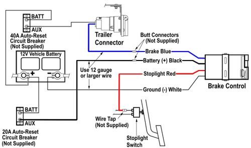
Wiring the 7-Way Trailer Connector and Brake Controller
1. Return to the duplex cable under the hood, where the brake wire (now white) needs to be separated from the 12 volt hot lead (black).
- The 12 volt hot lead will stay under the hood, where it will be connected to the positive post of the battery via a 40-amp circuit breaker.
- The brake wire will be routed through the firewall into the vehicle, where it will later be connected to the brake controller.
- It is best to run the brake wire through an existing grommet or knockout in the firewall.
- If none is found, a hole can be drilled.
- Make sure both sides of the firewall are clear of obstruction before drilling.

2. Using a butt connector, connect the blue wire coming out of the brake controller to the brake wire (white wire of the duplex cable) that was routed through the firewall.
3. Find a safe location under the hood or on the firewall to mount two circuit breakers: one 20-amp (or 30-amp; see brake controller instructions) and one 40-amp.
- After those are secured, route the 12 volt hot lead to the 40-amp breaker via ring terminals and then to the positive post on the battery.
4. The black wire coming out of the brake controller is the brake controller power supply.

- Route this wire to a 20-amp (or 30-amp) breaker under the hood and then to the positive post on the battery.
- There are now two wires connected to the positive post: the 12 volt hot lead and the brake controller power supply.
- NOTE: There will be excess wire after the 12 volt hot lead or brake wire connections have been made.
- If any brake controller wires are too short, use the excess wire from the 12 volt hot lead or brake wire to lengthen them as needed.

5. The white wire coming out of the brake controller is the ground wire.
- Route this wire to the negative post on the battery.
- It will be too short to reach the battery, so you will have to use excess wire from the 12 volt hot lead or brake wire to complete this connection.
6. Inside the cab, we only have one connection remaining.
- Find the wires connected to the brake switch at the top of the brake pedal.
- Using a circuit tester, find the wire carrying a signal when the brake pedal is engaged.
- Use a quick splice to connect this wire to the red wire coming out of the brake controller.
7. With the brake controller mounted and connected, zip tie any loose, excess wires underneath the dash and under the vehicle.
- DO NOT allow the wires to interfere with the brake and gas pedals, and keep them away from areas of excessive heat.
Source: https://www.etrailer.com/faq-installation-of-brake-controller-from-scratch.aspx
Posted by: enochkrein.blogspot.com